

 英语
英语 法语
法语
Address
No.148 Yongda Road, Jiangkou Street, Huangyan, Taizhou, Zhejiang, China.
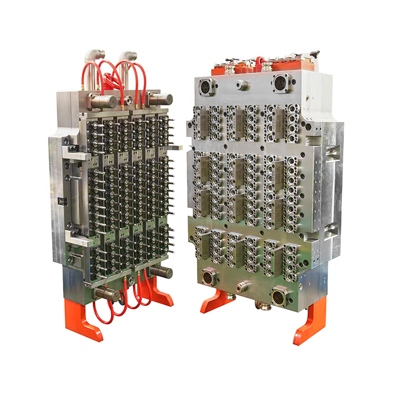
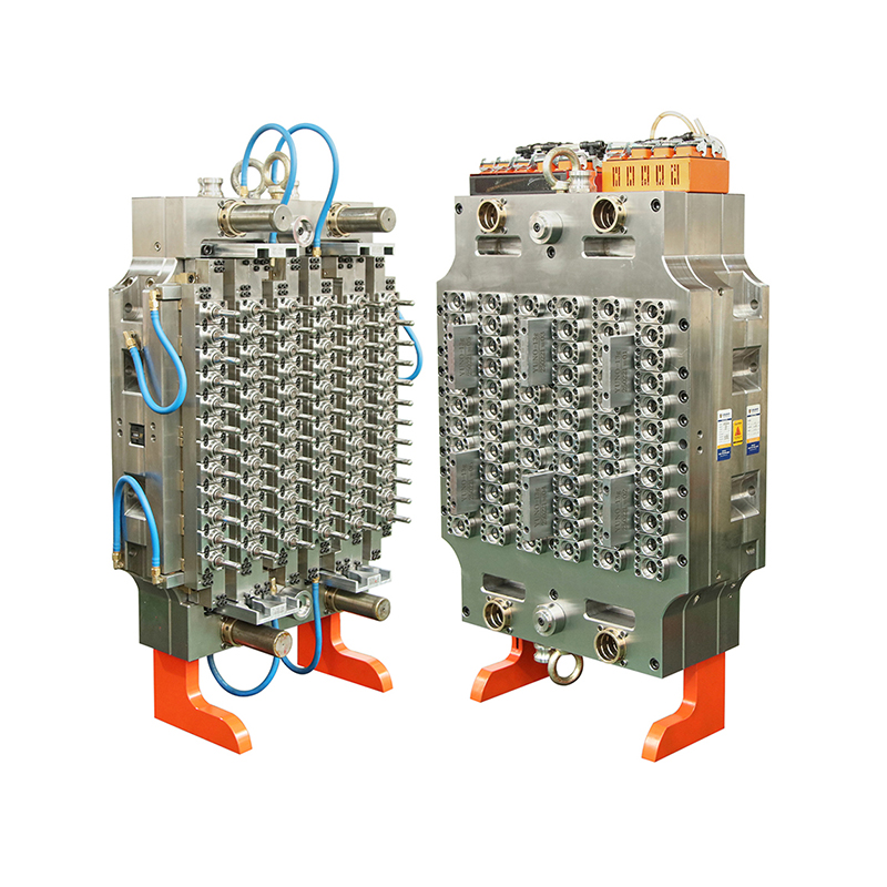
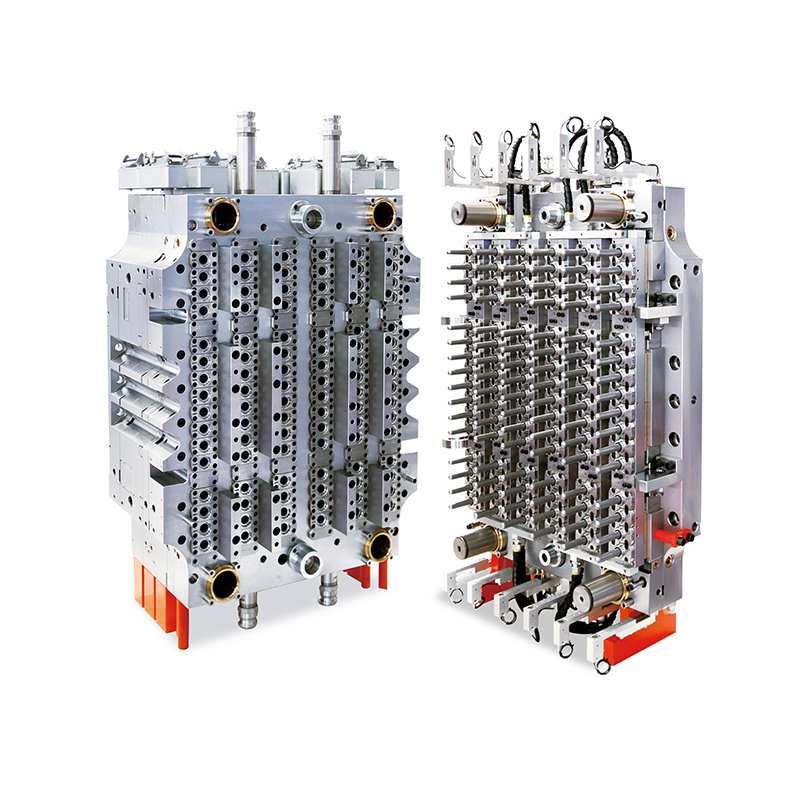
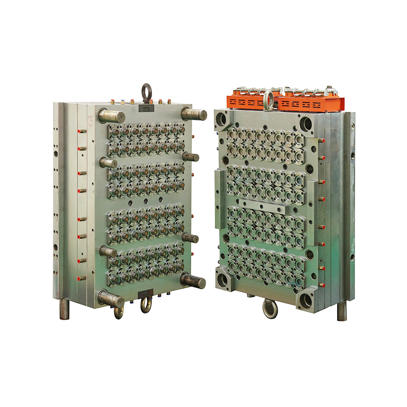
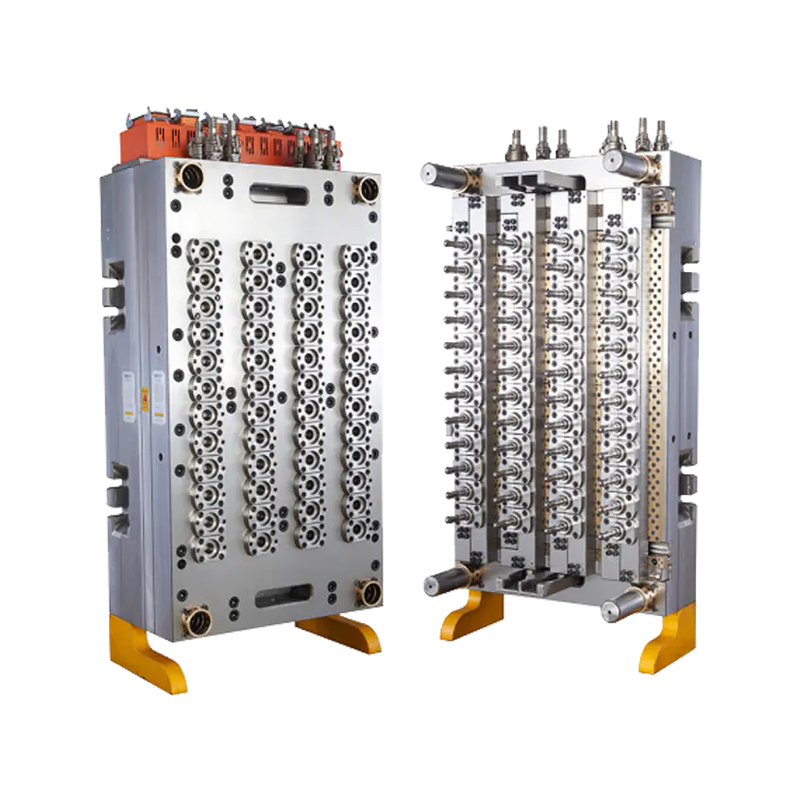
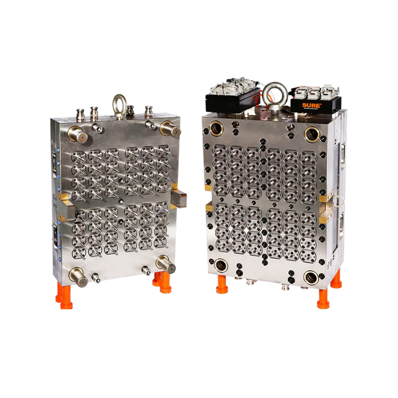
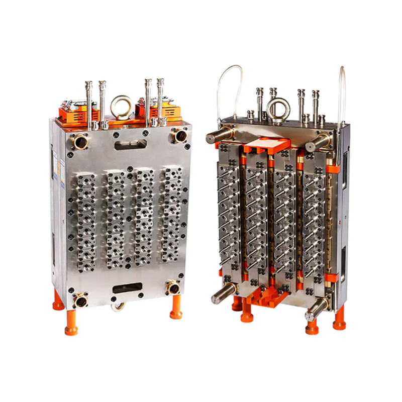
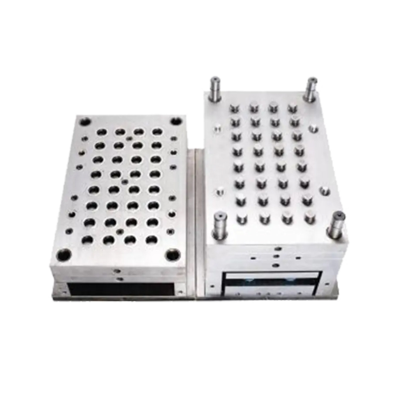
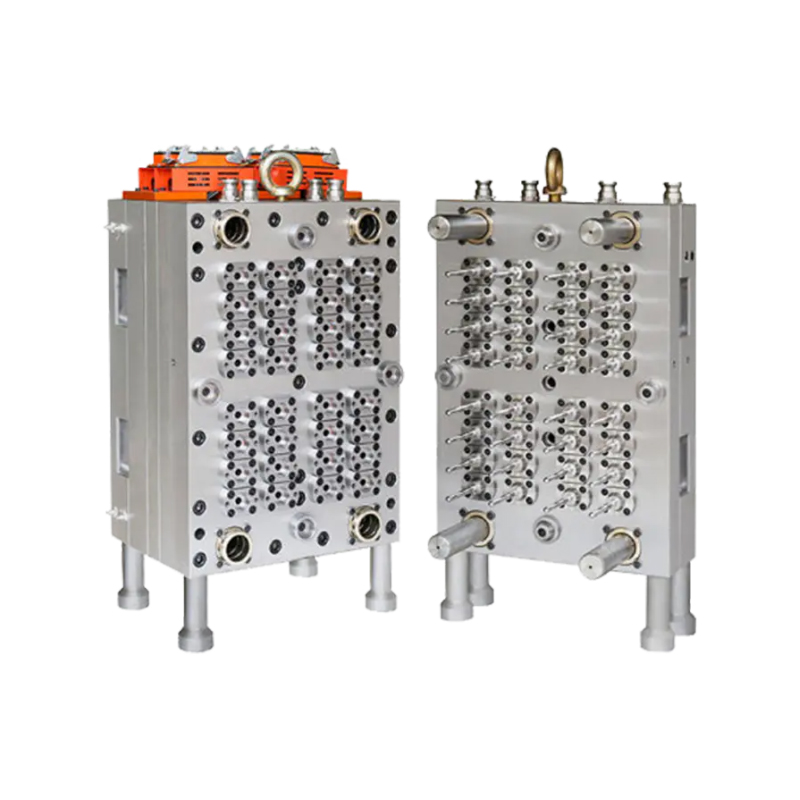
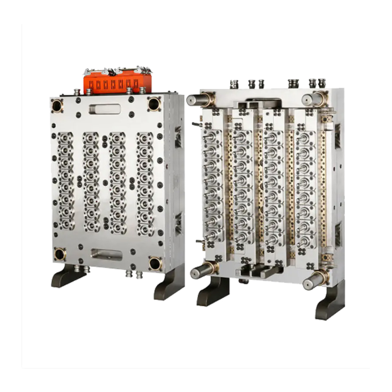
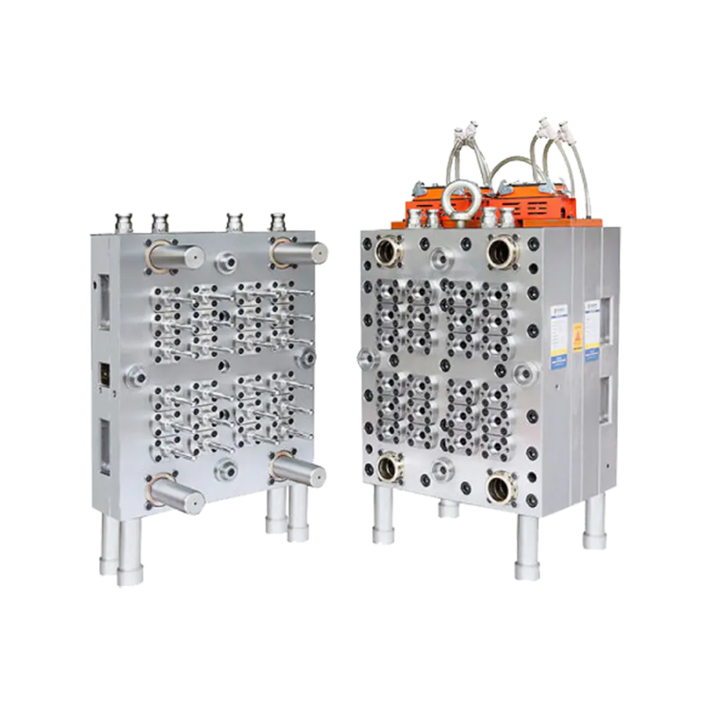
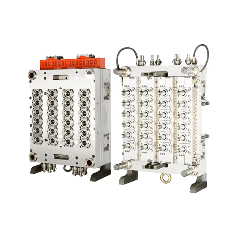
A cap mold forms the foundation of how plastic closures are produced at scale, shaping everything from bottle caps to container lids across countless industries. The design of a cap mold determines not only the final shape of the product but also how quickly and consistently a manufacturer can turn out finished parts. For companies producing closures in high volumes, the mold itself often becomes the single most important piece of equipment on the production floor.
The internal structure of a cap mold involves precise channels for cooling, venting, and material flow. Molten plastic enters through a gate system and travels into individual cavities, where it takes the shape of the cap before cooling and solidifying. Engineers pay close attention to wall thickness and gate placement, since uneven flow can lead to warping or incomplete fills during the injection process.
Cooling channels running through the mold body play a particularly important role in cycle time. A [cooling channel diameter] is often calculated based on the cap's wall thickness and the material being used, since faster, more even cooling allows the mold to open sooner and start the next cycle. This balance between speed and structural integrity is central to how cap mold systems are engineered for continuous production.
Not all caps require the same mold structure. Simple flat caps used for bottled beverages often rely on straightforward single-piece mold designs, while flip-top or dispensing caps require more complex tooling with moving components like slides or lifters. These additional mechanisms allow the mold to form undercuts or hinges that wouldn't be possible with a basic cavity and core setup.
Threaded caps, which need to screw onto a corresponding container neck, introduce another layer of complexity. The mold must include unscrewing mechanisms or collapsible cores to release the finished cap without damaging the thread pattern. Manufacturers producing a wide range of cap styles often maintain multiple mold configurations to accommodate these differing structural demands.
Cavity layout within a cap mold directly affects how many parts can be produced per cycle and how evenly material distributes across the tool. A balanced layout, where cavities are arranged symmetrically around a central gate or runner system, helps maintain consistent fill pressure and reduces the chance of short shots in cavities positioned farther from the injection point.
For manufacturers running high-cavity molds, layout planning becomes even more critical. A [cavity count range] is typically chosen based on the machine's clamping force and the size of the cap being produced, since packing too many cavities into a single mold can strain the injection system. Careful spacing also allows technicians easier access for cleaning and adjustments between production runs.
In industries where closures are needed by the millions, such as beverage bottling or personal care packaging, cap mold systems are built to withstand continuous cycling without losing dimensional accuracy. Materials used in the mold itself, often hardened tool steel, are selected specifically to resist wear from repeated contact with molten plastic under pressure.
Production teams working with these systems typically monitor cycle consistency closely, since even small shifts in cooling time or material flow can affect part quality across thousands of cycles. This attention to detail throughout the cap mold's operational life is part of what allows manufacturers to keep output steady while meeting the specific dimensional requirements each cap design demands.

No.148 Yongda Road, Jiangkou Street, Huangyan, Taizhou, Zhejiang, China.

yn@tzyuno.com

+86-576-84111565

+86-13575806039


Copyright © Taizhou Huangyan Yuno Mould Co., Ltd.
Plastic Mould Factory